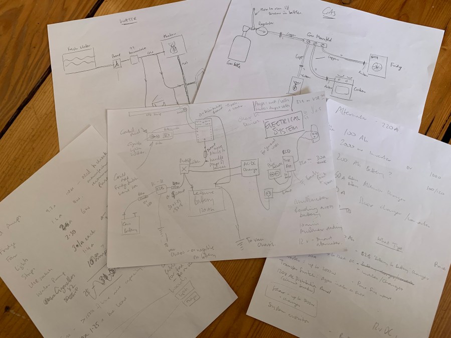
Before we could install the walls and ceiling we needed to install the electrical system, as all the wiring needs to be run along the inner skin of the van. This meant that first we had to consider the following:
- Deciding on the devices we want to use and install (from lights and power points, to devices like the heater and water pump)
- Calculating the power usage of all devices to determine a suitable sized leisure battery
- Planning their various positions in the van (this will determine wire type and thickness, as well as where to cut holes)
- Calculating the electrical current and power usage of each device – to determine which thickness of wire to use, and size suitable fuses
- This included calculating the voltage drop for each device
- Planning the position of the battery and charging system, as well as the position of the external hook up point (electrical hook up, or shore power, at campsites)
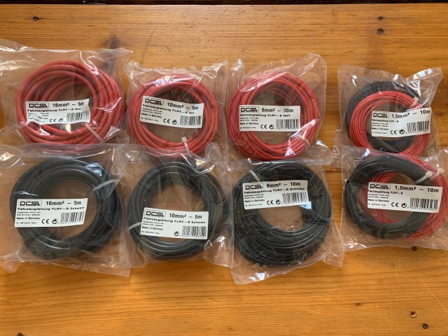
Each device requires the correct thickness of wire, which is primarily determined by the amount of current the device requires. You also have to take into account the length of the cable between the device and power source and a phenomenon called voltage drop, which is:
“the decrease of electric potential along the path of a current flowing in a circuit”
Simply put, as electricity travels through the wires some of the power and available current is lost due to the resistance of the wires and components.
Excessive voltage drop may result in the unsatisfactory performance of the devices and, critically, overheating of the wires and connections. Meaning that the further the distance of your devices from the power source (leisure battery) the thicker the wire you need to use.
Another complication is that the system will use mains alternating current (AC), or shore power, to provide a power source and charge a leisure battery that will provide direct current (DC) to power the main devices.
In addition, some devices will also need to run directly off the mains power, and we planned on adding mains plugs too.
Once the plans were complete it was time to order the required parts and start building.
The Test Build
We started out by building a test system as a proof of concept and we also took an overnight trip to a local campsite just to check the integrity of setup.
This is the basic test system and consists of:
- Leisure battery – main source of power for the van
- Battery gauge
- RCB or residual circuit breaker (white box) – connected to shore power and mains plugs inside the van
- Shore power connector – plugin point at campsites
- Charger (blue device) – this plugs into the circuit breaker and charges the leisure battery
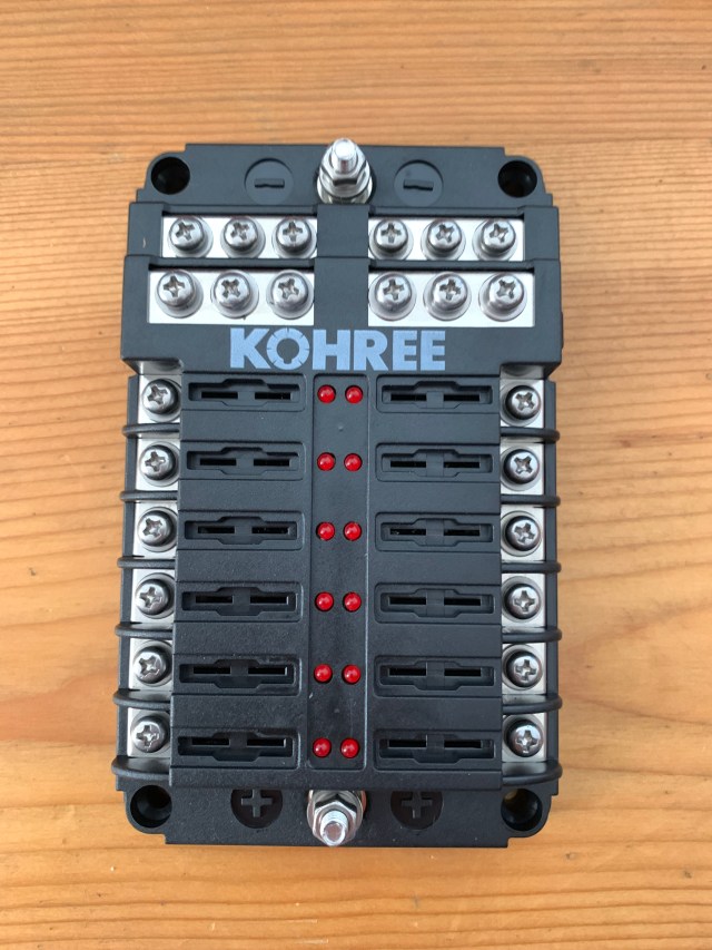
- Fuse relay (DC distribution board) – connects directly to the battery, then to our components/devices via fuses
- Isolation switch and in-line fuse to allow disconnection of battery when not in use
- Test lights connected to the fuse relay
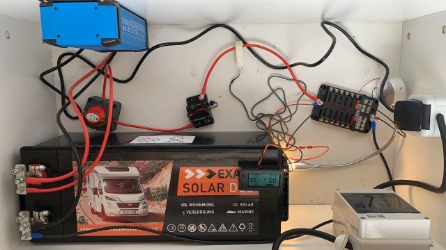
We’re happy to report that this worked perfectly, well mostly. With our first attempts we learned the importance of good crimping technique and making sure that all wire ends and connectors are firm and secure. With the DC connections there isn’t much risk of electrocution, but you don’t want connectors hidden behind walls and ceilings to come loose.
The Installation – Phase 1
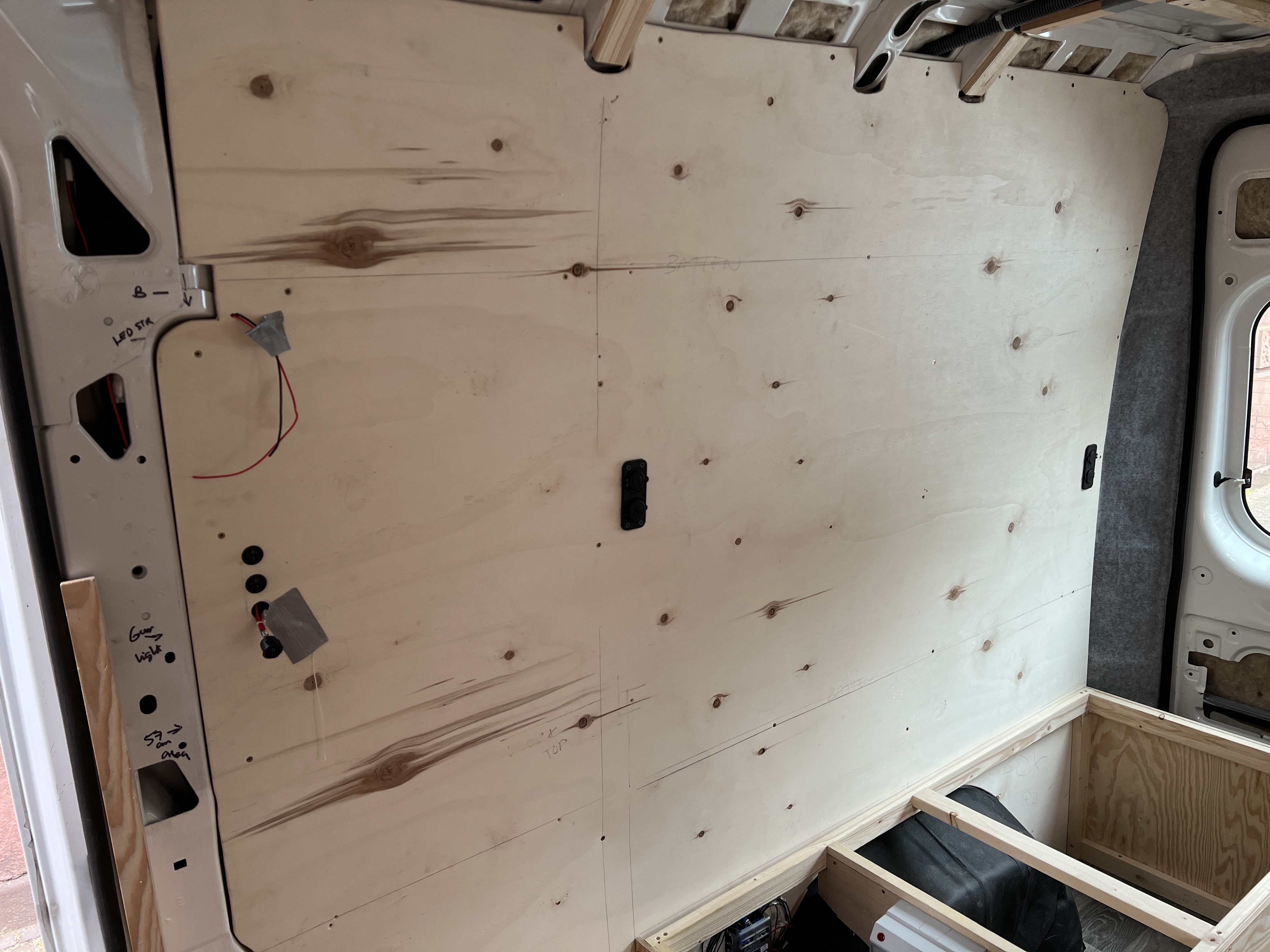
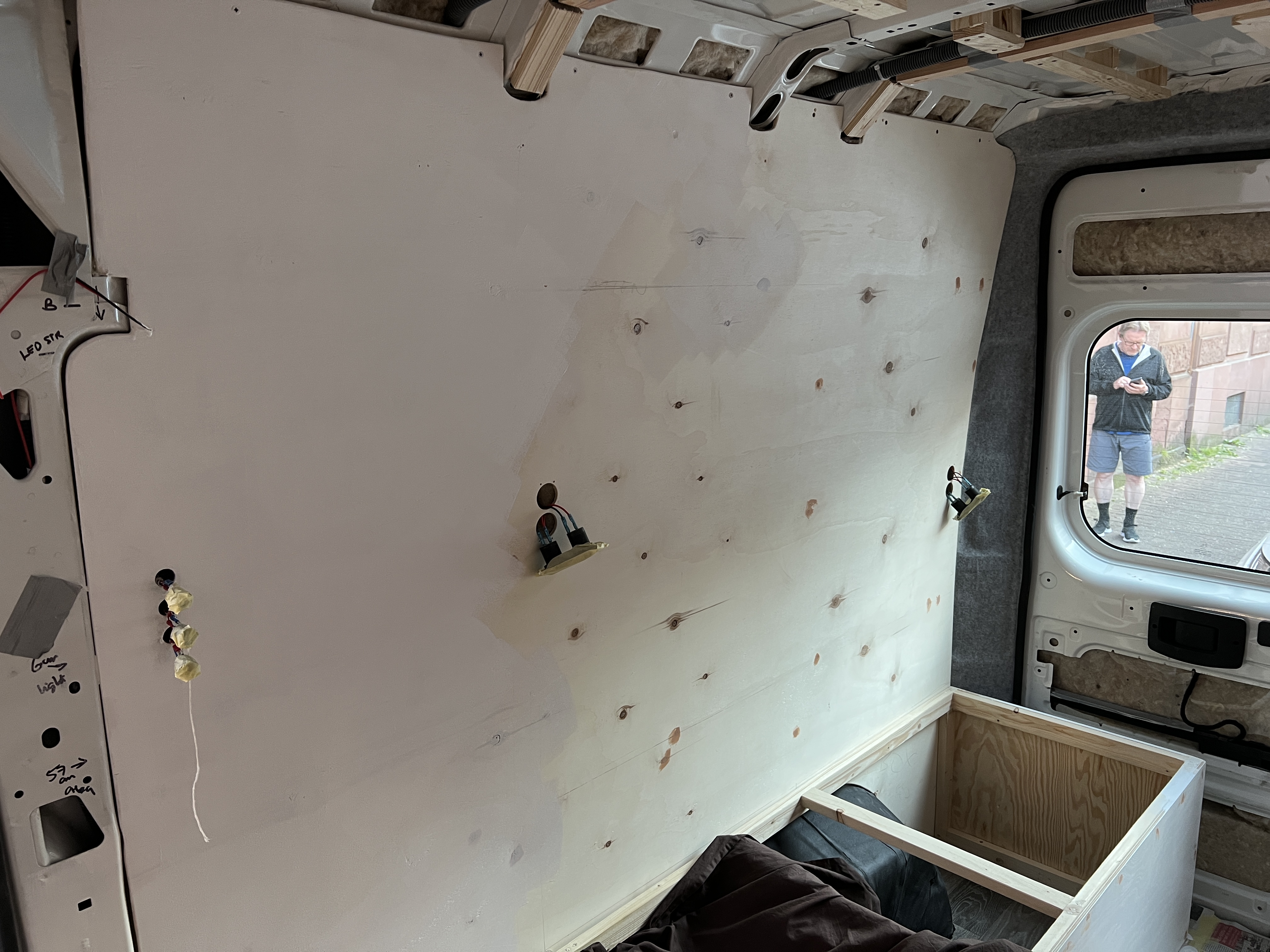
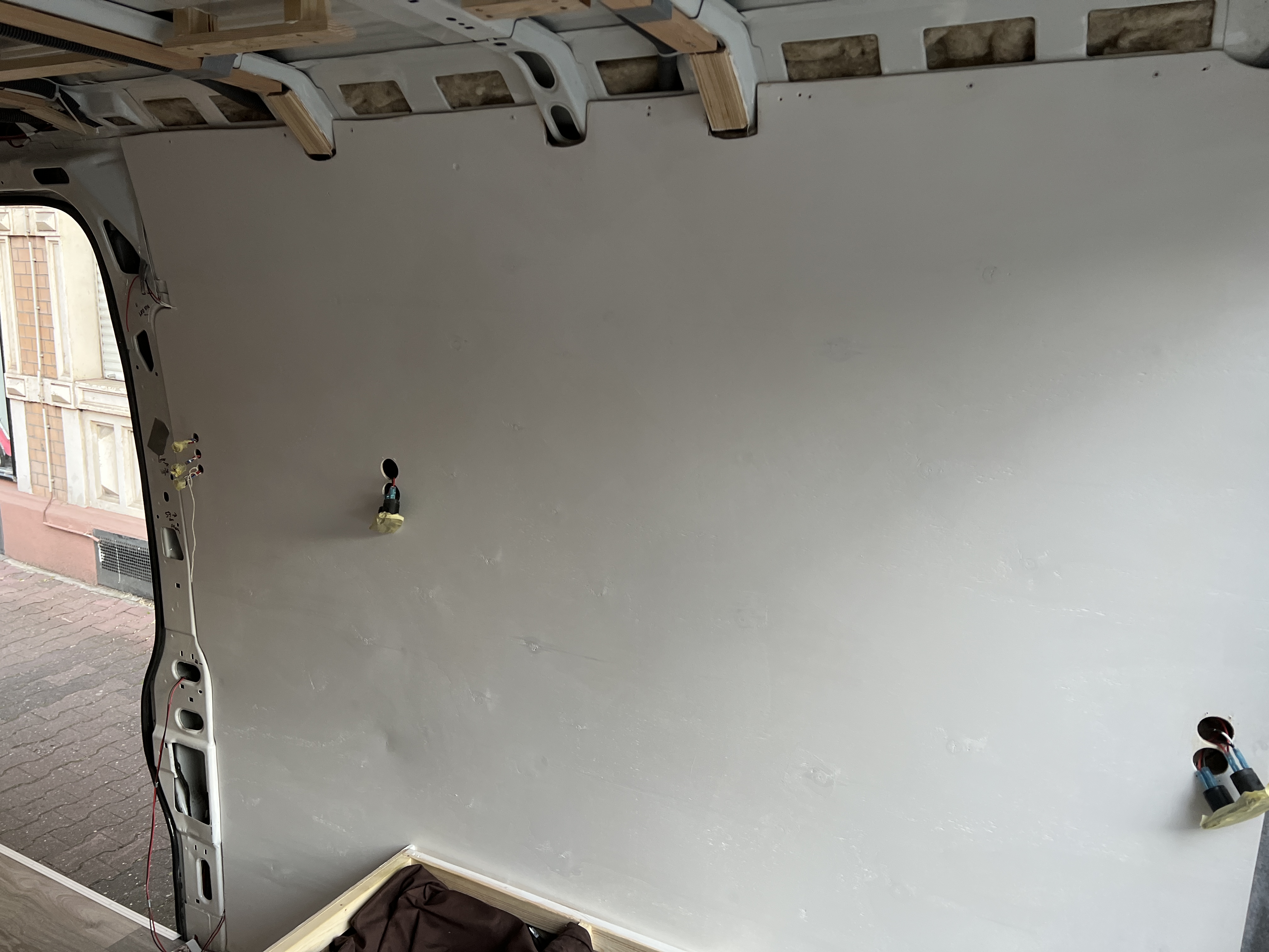
Once we were happy with the proof of concept the next step was to start laying the wiring along the walls and ceiling. This would be done using plastic ducting to house the wires so that they would not be in direct contact with the sheep-wool insulation we would be inserting between the walls and external skin of the van.
For this we used 25mm diameter fire-resistant flexible tubing as it would easily bend around the curves of the van without deforming. It was also very easy to cut, only requiring a good Stanley-type knife.
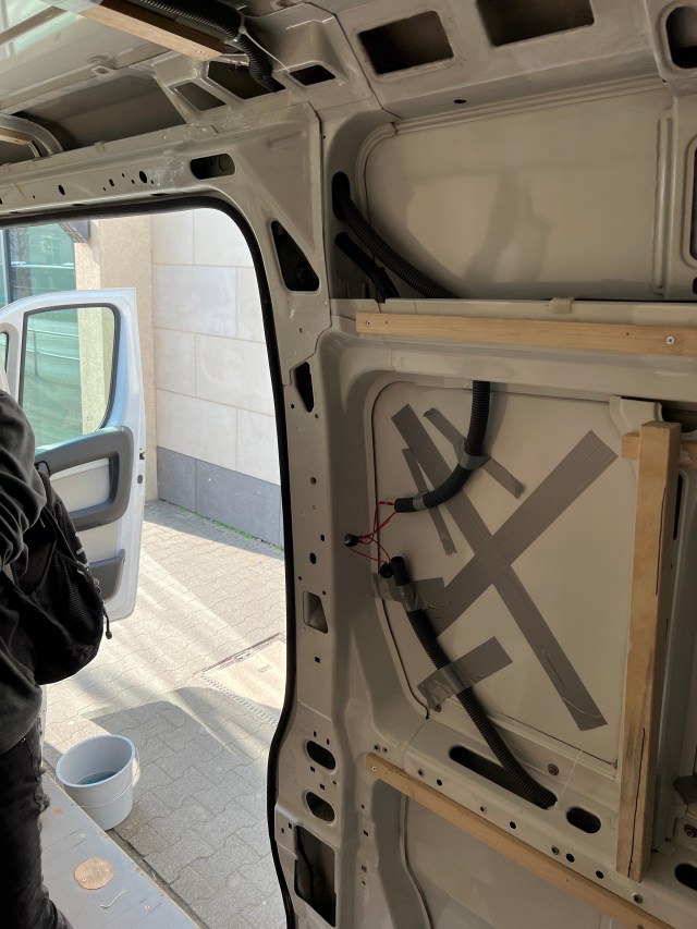
Using ducting would make it easier to repair and replace wires in the future, as we could just thread or pull them through the tubing rather than have to remove the walls and ceilings. This would also ensure that the wires have enough air around them to prevent any reduction in current carrying capacity.

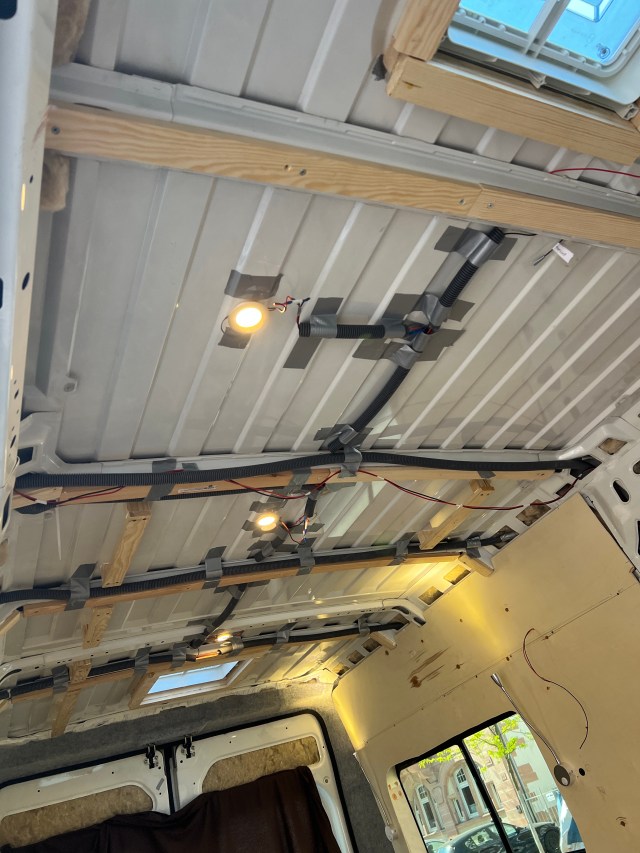
The duct tape might look untidy but it was the best method we could find to attach the tubing to the walls and ceilings without drilling through them. The tape is lightweight and reliable, plus no one will ever see it. Again!
Each wire had to be carefully labeled at both ends so that we didn’t mix them up when finally connecting each to the required devices at one end, then to the relevant slot on the DC fuse box at the other. Each device draws a different amount of current and so requires individual fuses to make sure they work properly. The fuses also prevent any overload in the wires, which could damage the devices themselves or, more critically, start a fire by melting the wires.
Placing the wiring and connectors took many, many hours, over many, many days, but with the wiring finally in place, we could start feeding them through the relevant positions in the walls and ceilings when installed (this will be covered in the next post) and start connecting our electrical devices.

All devices, switches, and power points ultimately connect to the most important part of the system – the heart of the electrical system.

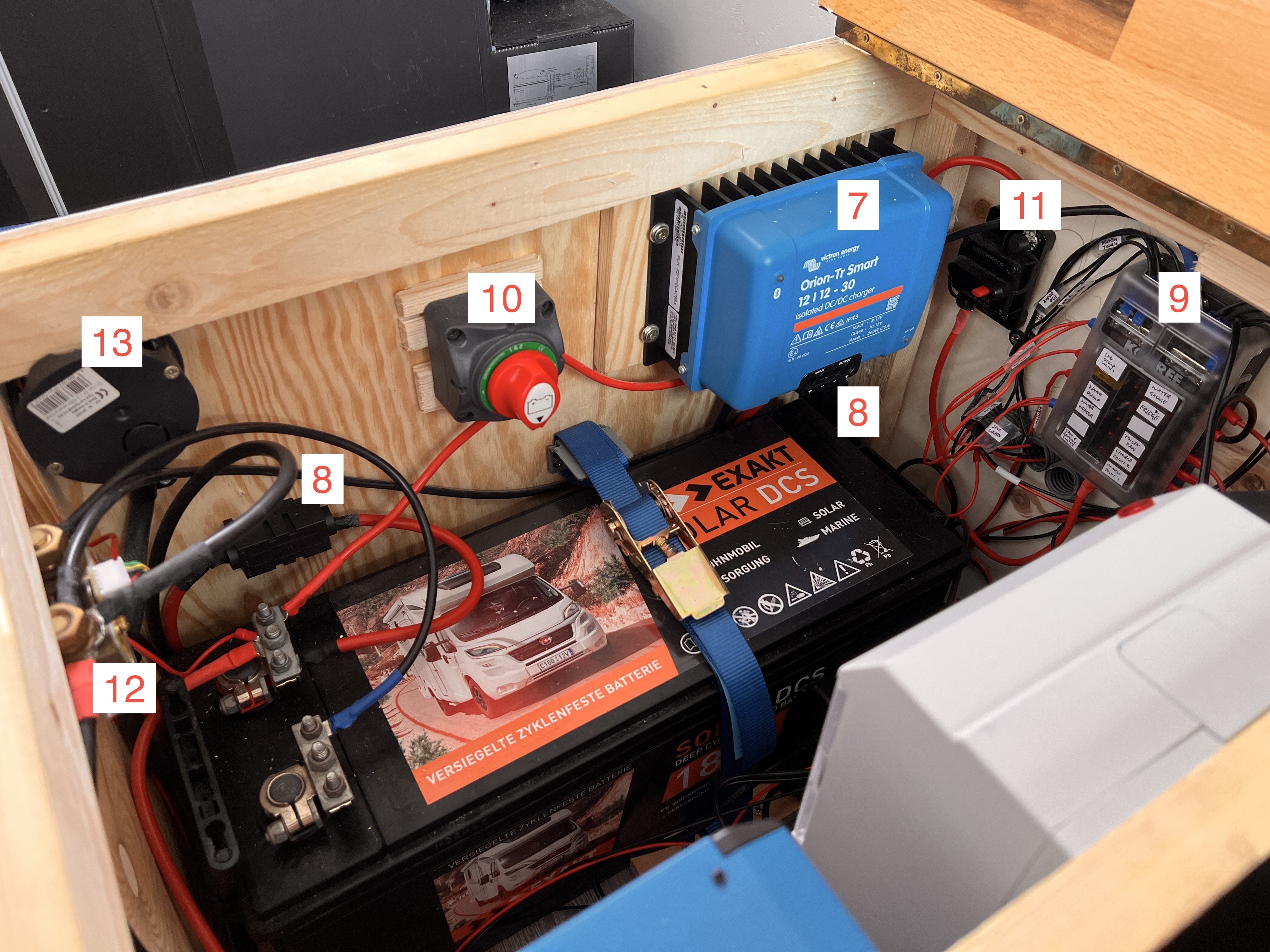
Device List
- Double-pole RCD Circuit breaker – connects the 210/240V input voltage from shore power, with plug outputs
- Plug connector from circuit breaker to battery charger
- AC to DC battery charger – charges the leisure battery from mains power
- Leisure battery – main power point for all DC appliances
- and 9. DC distribution panel and circuit breaker – fuse box for all DC connections
- AC plug for condenser fridge (also runs on DC from the DC panel)
- DC to DC battery charger – charges the leisure battery from the van’s alternator whilst driving
- In-line fuses between the van’s alternator and DC leisure battery charger
- See no. 5.
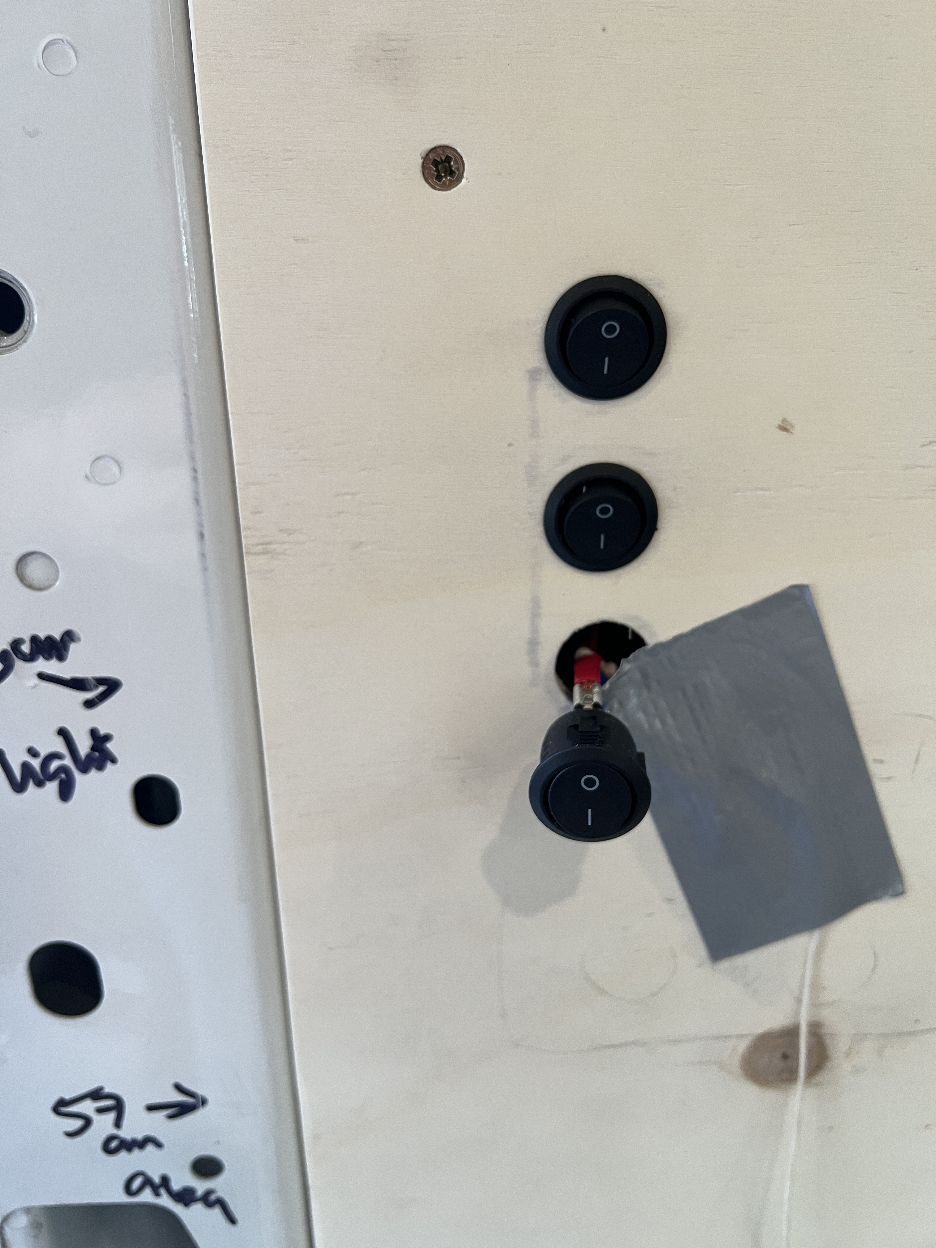
- Isolation (on/off) switch
- In-line circuit breaker – between the leisure battery and DC distribution panel
- Battery monitor shunt – connects to the battery gauge
- AC plug (1 of 2) – runs on 210/240V when plugged in to shore power, allowing use of household appliances
Minimum Viable Product (MVP)
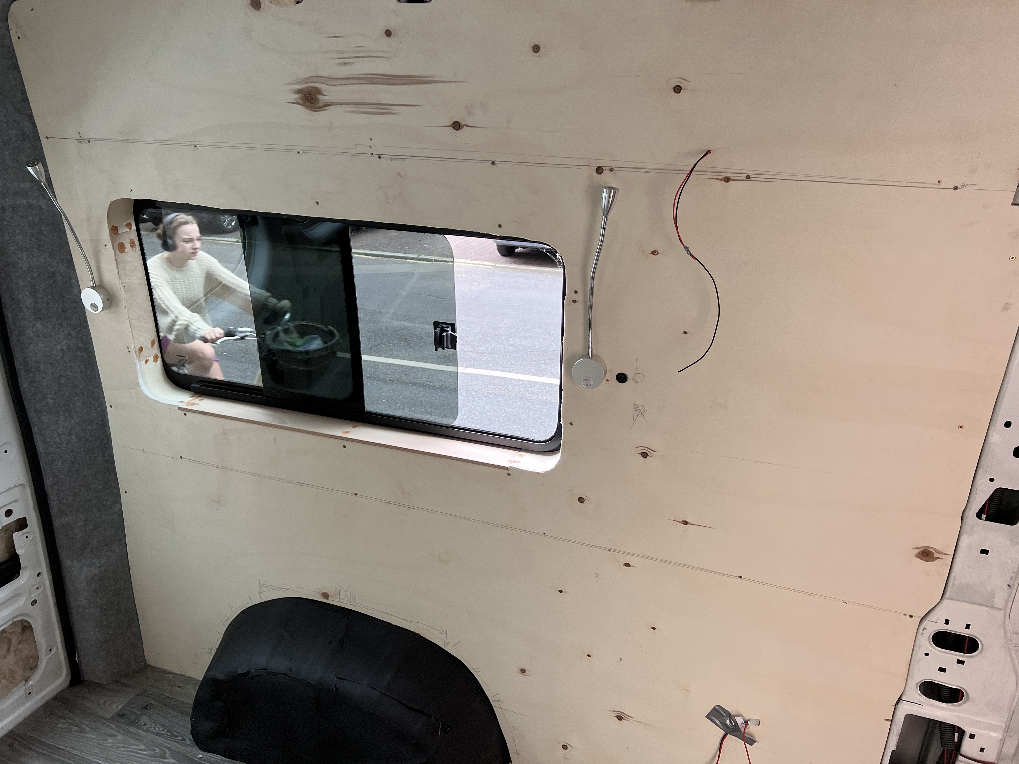
This is our basic system, or MVP system, with AC power points, battery charger, USB power points, and basic lighting system (spot lights and reading lamps), everything we initially need to live comfortably in the van. Future expansion of the system will include the following additions:
- Phase 2 – connecting the diesel heater
- Phase 3 – connecting the water systems – pumps and water heater (including shower, sinks, and toilet)
- Phase 4 – solar panels (for off-grid camping)
- Phase 5 – additional interior lighting
- Phase 6 – possible addition of an inverter (to convert DC battery power to AC)
These upgrades will take the van from a simple, comfortable summer camper, to a luxurious all-year, all-weather, and ultimately off-grid camper. All of these have been fully planned and connecting wiring is in place, all that’s needed now is the parts and the time to install them.
You can see the full gallery here.
Next steps
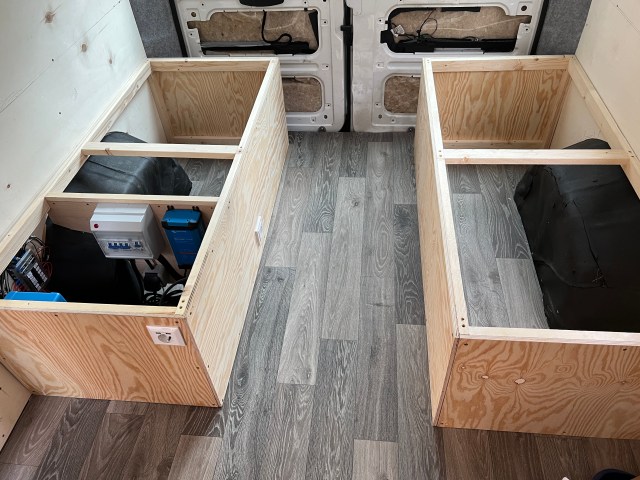
As part of this process we had to put up some of the walls, part of the ceiling, and create the initial stages of the bed/seating boxes. Now it’s time to finish these, and you can read about these steps in our next series of posts.

Looks pretty awesome so far! Was the sheep’s wool insulation an eco choice or something else? Does its compare well with alternatives like mineral wool? Asking for future outside workshop plans 🙂
LikeLike
Thanks Tom. We went for sheep wool mostly because it’s an eco product and we’re trying to be as sustainable as possible. There were a number of other different reasons we chose it as well – it’s waterproof and breathable, insect proof, gives the same (if not better) insulation properties per unit volume than synthetic varieties, it’s safe to handle without specialist equipment, and is hypoallergenic too. I was also reading that it is naturally flame resistant and self extinguishing, though we’re hoping not to put that to the test.
We got ours from a place in Brecon, I can give you the details if you like.
For the flooring insulation we’ve used cork tiles for exactly the same reasons as with the wool, plus the sound-deadening properties.
LikeLike
Pingback: Walls, ceiling, and window frames – Viamkarlito